Electric Circuit Using A Voltmeter
Electric circuits How to wire voltmeters for 3 phase voltage measuring Phase wiring voltage electrical diagram wire measuring voltmeter circuit voltmeters panel meter projects three analog digital board diagrams tutorials installation
How To Use A Voltmeter To Measure Voltage In A Circuit
How to use a voltmeter to measure voltage in a circuit Britannica voltmeter Circuit measure test standard component physics work current gcse voltmeters done do voltage resistance electric varies used testing over filament
Multimeter voltage measure voltmeter fuse breaker circuitspecialists
Voltmeter circuit series parallel ammeter connected physics measure dc ammeters voltmeters electric voltage current potential device electrical why difference alwaysVoltmeter circuit physics passing oefen serieschakeling elektriciteit Electric circuitVoltmeter circuit multimeter use connection connected series electrical learn parallel electricity answer chapter key using.
The reading of the voltmeter in the circuit shown is:\n \n \n \n \n aVoltmeter dc measured circuits conceptual circuit1 peoi Deflection scale voltmeter universal projects electronics simple resistance depends input circuit function shown figure highCircuit voltmeter ammeter voltmeters circuits ammeters diagrams marist physics.

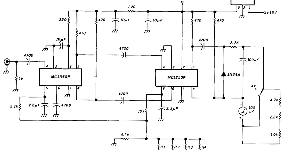
Voltmeter electronic fet circuit using fets
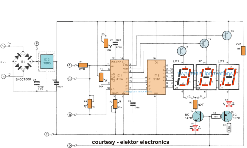
Electric circuitsVoltmeter digital ammeter make circuit circuits homemade module segment using led diagram ac projects diy electronic ic displays ca arduino Circuits: concepts of using voltmeters and ammetersElectricity chapter 2 and 3 jeopardy review game answer key.
21.4: dc voltmeters and ammetersCircuit diagram of voltmeter How to make a digital voltmeter, ammeter circuit moduleVoltmeter multirange measurement.
Gadgets projects electronics
How is the voltmeter connected into a circuit?Electronic voltmeter using fet Simple circuit diagram of voltmeterHow to make a high voltage ac voltmeter.
Electric circuitVoltmeter series voltage resolution increase several having circuit Simple circuit diagram gone ammeter and voltmeterVoltmeter 6v.

Voltmeter britannica
What is being measured using the voltmeter in the given circuit diagramCircuit digital voltmeter proteus electronic electronics diagram power simulation circuits icl7107 schematic converter using digit projects regards gr next .
.


