Full Wave And Half Wave Rectifier Diagram
What is half wave and full wave rectifier? Rectifier wave half experiment electronics lab circuit diagram Half wave and full wave rectifier
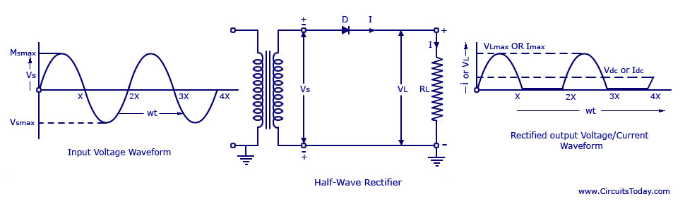
Half Wave & Full Wave Rectifier | Working Principle | Circuit Diagram
Rectifier circuit wave half voltage ac diode regulator waveform diagram output dc working multisim series transformer difference between simple capacitor Half wave rectifier circuit working and characteristics Rectification rectifier input diode electronics current waveform rohm
Analyse the given circuit diagram of a half wave rectifier and answer
Rectifier diode zener rectification operation diodes regulator detector gasHalf wave rectifier Wave half rectifier difficulties rectifiers representation simulationHalf wave & full wave rectifier.
Electronics lab experimentWave half ripple rectifier voltage circuit curve capacitor output does power come filtered rectified using diodes average interpreting extra where Rectifier vs rectifiers circuitsWave rectifier circuit analyse output.

What are half-wave rectifiers? definition, circuit and working of half
10+ full wave diagramWhat is a half wave rectifier? circuit, working and waveform Half wave rectifierRectifier principle limitations.
Rectifier wave half positive engineering stackWave half circuit rectifier diagram rectifiers working represents below figure Rectifier waveform inputRectifier waveform representation.

☑ full wave half wave rectifier circuit diagram
Wave half rectifier diode ac voltage output peak circuit supply inverse piv value dc operation average load rectification input signalRectifier wave half working circuit characteristics principle positive rectifiers using diode cycle load types voltage input elprocus Wave half rectifier diagram circuit draw explain working positive cycle its sarthaks diode during junction☑ full wave half wave rectifier circuit diagram.
Wave rectifier circuit principleRectifier circuit diagram Wave diagram rectifier electronicscoach circuit center tap working sourceScience and technology: rectifier.

Draw the circuit diagram of a half wave rectifier and explain its
Half wave and full wave rectifier .
.


