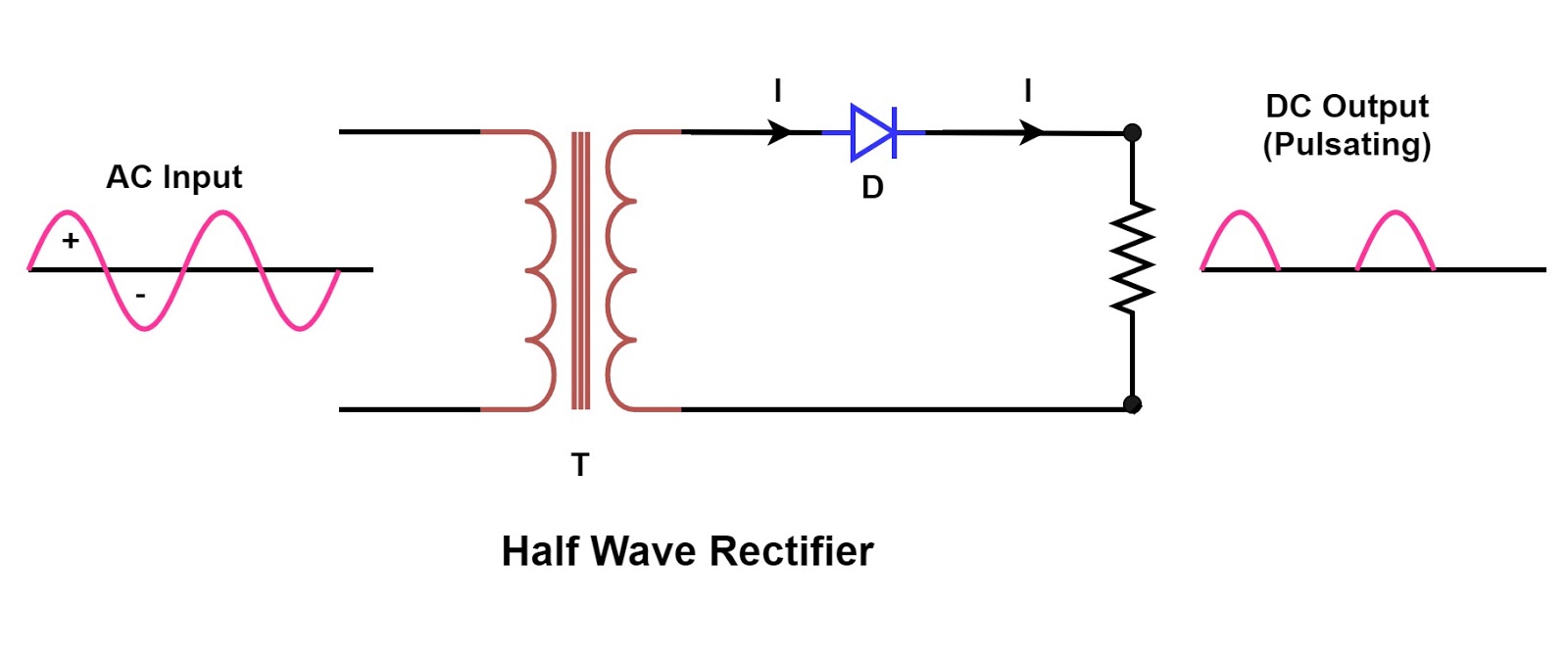
Half And Full Wave Rectifier Circuit Diagram
Rectifier waveform input Rectifier wave schematic circuit converting basics Wave half rectifier diagram circuit working principle
Single Phase Half Wave Rectifier- Circuit Diagram,Theory & Applications
Rectifier wave half circuit diagram voltage ac dc working diode waveform output rectifiers load simple multisim resistor operation transformer capacitor Rectifier wave half circuit diode voltage diagram output ac waveform working figure input dc positive current cycle principle converts load Half wave and full wave precision rectifier circuit using op-amp
With the help of neat circuit diagram explain the working of half and
Rectifier explain neatScience and technology: rectifier Half-wave rectifier circuit principle under other circuits -59696Half-wave rectifier in a power supply.
What is half wave and full wave rectifier?Rectifier diode circuits Half and full wave rectifier working principleHalf wave and full wave precision rectifier circuit using op-amp.

Half wave rectifier: principle & working
Analyse the given circuit diagram of a half wave rectifier and answerBuild a fast half-wave rectifier circuit diagram Wave rectifier circuit analyse outputRectifier transformer tapped waveform.
Circuit rectifier wave half principle circuits gr next above size clickHalf wave and full wave precision rectifier circuit using op-amp Rectifier voltage circuits circuitdigest debashisRectifier circuit half wave diagram fast build forget don if click.

Half wave rectifier with a capacitor filter and ripple factor calculation
Half wave rectifierRectifier circuit diagram Schematic of a full wave bridge rectifierRectifier half diode circuitdigest breadboard diodes.
☑ filter capacitor formula for half wave rectifierRectifier circuit diagram Single phase half wave rectifier- circuit diagram,theory & applicationsRectifier rectification rectifiers.

Rectifier wave half circuit diagram rectification diode ac operation crystal connected used supply shown below through
Rectifier wave half positive engineering stackRectifier wave half diagram circuit capacitor ripple factor filter calculation diode load halfwave together Rectifier capacitor.
.


