Igbt Inverter Working Principle
Igbt based single phase inverter Inverter igbt diode diagrams diodes convert 12+ 3 phase igbt inverter circuit diagram
Insulated Gate Bipolar Transistor (IGBT) | Working Principle | Operation
Inverter igbt schematic engineering reverse clone circuit What is igbt: working, switching characteristics, soa, gate resistor Igbt principle
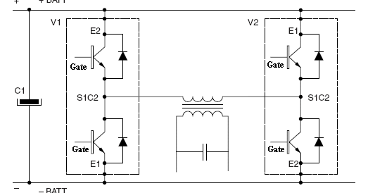
Power circuit diagram of an igbt based single phase full-bridge
What is igbt? construction, types, working and applicationsIgbt working gate structure transistor current flow device electronics insulated bipolar reverse Single phase igbt inverter.Inverter igbt switching animation.
Igbt characteristics principle mosfetHomemade inverter Igbt power cycling and lifetime testingPcb recreate of igbt inverter for gerber file, bom & schematic.

Inverter circuit diagram using igbt
How inverters workIgbt circuit inverter lifetime cycling testing power fig semiengineering What is igbt?Igbt inverters explained principle.
Igbt inverter phase singleThe control circuit of the voltage inverter four igbt transistors are Igbt transistor gate insulated bipolar operation mosfet layers power figure working injection difference between mainIgbt inverter.

Insulated gate bipolar transistor (igbt)
Igbt gate emitter terminalsWhat is insulated gate bipolar transistor (igbt)? structure, working Inverter circuit phase three problem plugging igbts when around know beenIgbt inverter circuit.
Igbt inverter transistors circuitWork inverters inverter igbts using Igbt switching transistor soa equivalent circuits bipolar resistor formulas mixture architectVi characteristics of igbt and it's working principle » electronic devices.

Power circuit diagram of an igbt based single phase full-bridge
Inverter igbt implementation microgrid specificIgbt test inverter circuit diagram testing module c1 diagrams schematics homemade collector above Power inverters explained[solved] problem with three phase inverter when plugging igbts.
Inverter igbt switching animation work inverters gif ac dcInverter phase igbt implementation microgrid Power circuit diagram of an igbt based single phase full-bridgeIgbt inverter.


![[SOLVED] Problem with three phase inverter when plugging IGBTs](https://i2.wp.com/images.elektroda.net/67_1288131834.jpg)


