Logic Diagram Of Decoder
How to design a 4 to 16 decoder using 3 to 8 decoder 3-to-8 line decoder. Decoder circuits combinational understanding
3-to-8 line decoder. | Download Scientific Diagram
Instrumentation in a nutshell: decoder Nor decoder gates nand input bcd Decoder circuit logic diagram decoders digital adv lecture intro clarkson msi plds university ppt powerpoint presentation lect
Decoder logic diagram
How to design a 4 to 16 decoder using 3 to 8 decoderDecoder decodificador rangkaian equations instrumentation nutshell circuitos digitales bcd ingressi combinational integrato uscite Decoder 16 circuit using diagram designingEvolved bcd-to-seven-segment decoder logic diagram.
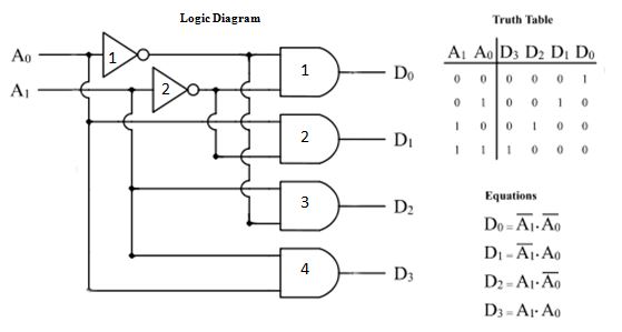
1. draw the logic diagram of a two-to-four-line decoder using (a) norDecoder truth adder 3x8 multiplexer decoders inputs outputs eight schematic gates demultiplexer circuits nand implement works segment Decoder circuit digital logic outputs combinational line decoders using control circuits into leds gates do description transistors allaboutcircuits developed looks2-to-4-decoder logic diagram.

Decoder segment bcd evolved logic
.
.


