Relay Driver Circuit Diagram
Uln2003 relay driver circuit ic using uln2003a diagram uln high channel integrated stepper transistor darlington pdf rd Relay 5v rangkaian songle arduino schematic skema modul relays aromat Relay uln2003 relays microcontroller
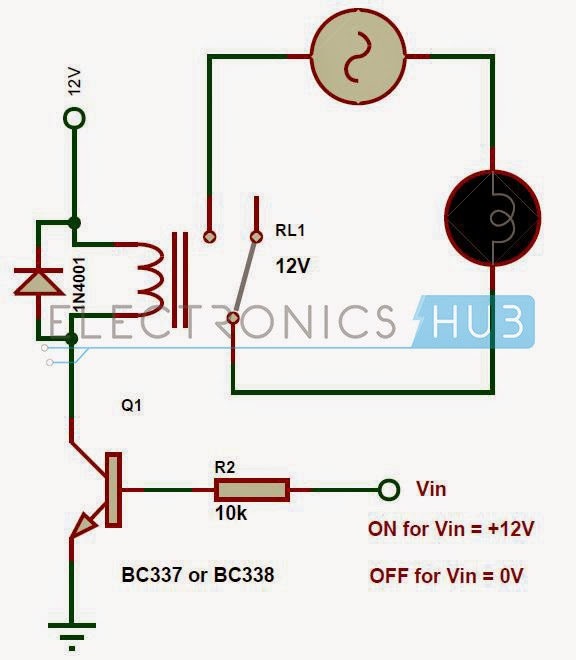
Transistor Relay driver circuit in digital | ElecCircuit.com
Relay circuit driver types relays diagram time electrical practical latching reed polarized choose board Relay driver circuit Drive relay by digital circuit
Relay arduino circuit driver proteus interface interfacing diagram module schematics label
Relay driver circuit diagram for applicationPower-saving relay driver circuit diagram 5 volt relay circuit diagramElectrical in practical ~ all time electrical.
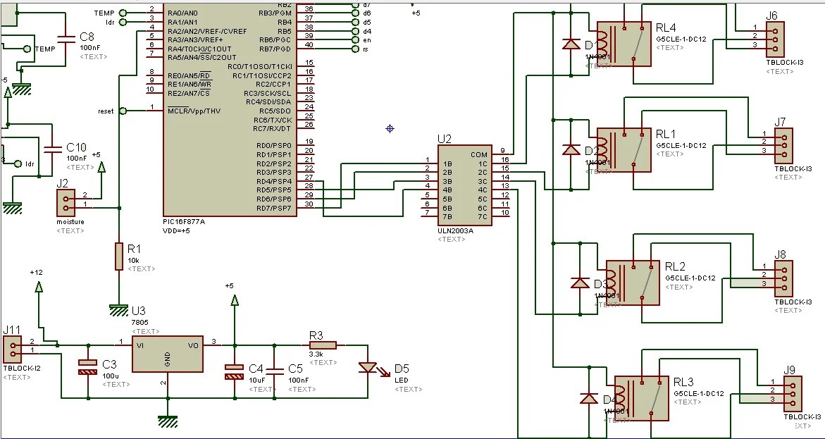
Circuit relay saving power driver diagram simple fig switch source transistorRelay driver circuit using ic uln2003 with applications How to interface relay with arduinoRelay driver circuit transistor step part.

Relay circuit bd139 bc549
Automatic change over by relay driver ic unl2003 with circuit diagramRelay transistor circuit driver digital current drive increase using circuits traffic light eleccircuit figure electronic darlington transistors two gain Relay wiring diagram and function explainedRelay driver circuit using uln2003 and its applications.
Relay circuit driver schematic diagram board dual channel circuits eewebDual relay driver board circuit schematic Transistor relay driver circuit in digitalArduino 5v input down.

How to drive a relay through an opto-coupler circuit
Relay opto coupler circuit drive circuits driver diagram darlington through homemade transistor projects12v relay wiring diagram 5 pin Relay 12v automotiveRelay driver circuit diagram uln2003 ic block using implementation practical switch.
Relay circuit drive driver digital eleccircuit figure electronic circuitsWiring understand .


