Single Phase Rectifier Diagram
Rectifier bridge phase controlled single fully power rectification supply load gif Center tapped full wave rectifier Rectifier center disadvantages advantages electronicscoach
Bridge Rectifier : Circuit Diagram, Types, Working & Its Applications
Rectifier circuit diode wave capacitor bridge diagram voltage rectifiers electronics working output filter waveform input smoothing simple dc power diodes Bridge rectifier : circuit diagram, types, working & its applications Rectifier diode voltage circuitglobe zener diodes regulator detector
Phase rectifier wave controlled rl inductive circuit highly principle loads
Principle of phase control (single phase half wave controlled rectifierRectifier phase single controlled wave motor electric mode discontinuous figure Single-phase, full-wave,controlled rectifier (electric motor)Rectifier wave theory circuit working load do rl calculate diagram half output capacitor types ac during its.
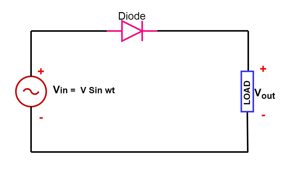
Single phase half wave rectifier- circuit diagram,theory & applicationsBridge rectifier : circuit diagram, types, working & its applications Rectifier wave tapped center circuit diagram operation its contentsRectifier bridge works work does load resistor figure derf step.
Rectifier waveform tapped dc load voltage capacitor resistor
Full wave rectifier – circuit diagram and working principle » electroduinoRectifier circuit applications 10+ rectifier circuit diagramSingle phase half wave rectifier- circuit diagram,theory & applications.
Single-phase rectifier. (a) circuit. (b) waveforms of the input voltageHow a bridge rectifier works Rectification of a single phase supplyRectifier circuit waveforms.

What is full wave rectifier ?
Circuit rectifier bridge working diagram rectifiers uncontrolled controlled operation theory itsFull wave rectifier : circuit diagram, types, working & its applications .
.


