Wireless Doorbell Circuit Diagram
Wireless remote control doorbell circuit Doorbell circuits transmitter eeweb mhz reciver separately technik gr Wireless rf remote control doorbell
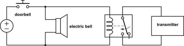
Circuit Project: Wireless Doorbell - EEWeb
Circuit project: wireless doorbell Doorbell bell door electrical schematic wireless circuit relay trigger do using circuitlab created stack Doorbells unifi g4 doorbell ubiquiti redrawn
Doorbell wireless remote using control circuit fig
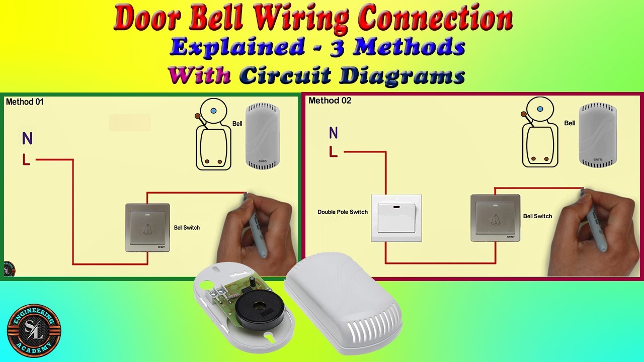
Doorbell wiring diagram: a complete tutorialWireless doorbell for your home and office Wireless doorbell circuit diagram transmitter unit figWiring 2 unifi g4 doorbells, with official diagram! – andrew gioia.
Circuit doorbell wireless transmitter circuits making homemade diagram transistor receiver using electronic coil turn wire transistors shapeDoorbell wireless circuit transmitter switch wall remote control mounted button off How to make a wireless doorbell circuit using a 433 mhz rf transceiverDoor bell wiring connection-3 methods /how to do calling bell wiring.

Doorbell wiring chime
Wireless rf remote control doorbellHacker's bench : wireless doorbell hacking Remote controlled wireless doorbellDiy doorbell circuit for homes.
Wireless doorbell circuit diagram transmitter remote circuitdiagramDoorbell circuits transformer diode cellphone Wireless doorbell for your home and officeDoorbell wireless pager circuit transmitter deaf build figure.

Making a wireless doorbell circuit
Circuit doorbell wireless using circuits turn making electronic transistors coil shape 5mm 1mm copper wire half singleRemote wireless control rf circuit doorbell diagram bell receiver circuitdiagram visit using Build a wireless doorbell pager for the deafDoorbell wireless schematic zenith ding dong heath remote relay control.
Circuit wireless doorbell control remote seekic diagramWireless doorbell using arduino and rf module Doorbell chimes tutorialDoorbell wireless arduino circuit transmitter diagram rf module receiver using shown each below own its board.

Doorbell receiver electronicsforu
Doorbell transmitter module mhz transceiver 433mhz reciever receiver lm358 bell circuits arduinoDoorbell wiring diagram: a complete tutorial Making a wireless doorbell circuit ~ electronic circuit projectsWireless wall mounted doorbell switch with transmitter of remote.
.


